
Rigging the Galley La Réale de France
Rope routing on the Heller 1:75 scale model
This article examines the construction and operation of Mediterranean galley rigging, using Heller’s 1:75 scale model of La Réale de France as an example. The model was built using plans and information from the French maritime museum, where a replica of the vessel is displayed.
My aim here is not to describe the history of the vessel or the construction of the model itself. Instead, I want to focus on its rigging. Galley rigging is distinctive and bears little resemblance to that of most other vessels. Mediterranean xebecs are perhaps the closest comparison.
The description covers supporting the masts, hoisting and turning the yards, and routing the lines used to control the sails. The article may also help readers understand the rigging of other Mediterranean galleys. However, the specific routes and numbering of ropes, blocks and rowing benches refer to the La Réale de France described here. For another vessel, its own plans and documentation should be consulted.
Galleys and Navigation in the Mediterranean
For thousands of years, galleys represented the pinnacle of oared naval warfare and were a dominant force in the Mediterranean. Their independence from the wind gave them excellent manoeuvrability and a tactical advantage in coastal waters. They gradually gave way to large sailing warships carrying heavy guns, which came to dominate the open oceans.
A 3D animation prepared for the French galley La Fleur de Lis of 1690 illustrates how rowing worked on these vessels. The animation and a description of the ship’s monograph can be found on Gérard Delacroix’s website. La Fleur de Lis was very similar to La Réale de France.
To gain a more immediate impression of the hardship and danger of life aboard a historical galley, you can visit the Museu Marítim de Barcelona. The museum displays a full-size replica of the Galera Real, or Royal Galley, the famous flagship of Don Juan de Austria at the Battle of Lepanto in 1571.
When I visited the museum many years ago, I was able to stand in the captain’s position. A scene showing oarsmen rowing on a rough sea was projected onto a translucent screen, accompanied by the sound of the sea and the drumbeat setting the rowing rhythm. It created a remarkably realistic impression. I can honestly say that I would not have wanted to be the captain either.
Rigging Plan and Blocks for the Heller Model
Using the plans of this vessel, I also prepared a set of special blocks specifically for this rigging. You can find the set in our accessories category for La Réale de France Heller 1:75.
To follow the individual rope routes, you can download the complete rigging plan for La Réale de France, which also identifies the blocks included in our set. The numbers used in the following description refer to this plan.
Shrouds and Backstays[1] – Fig. 1
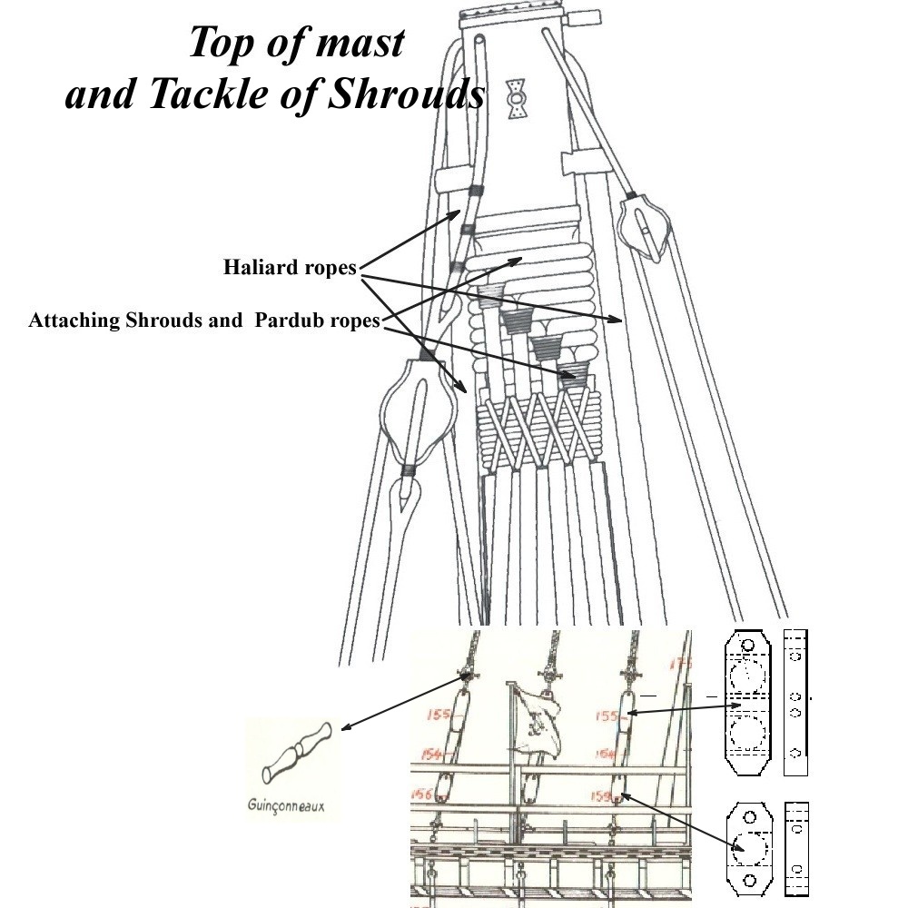
Let us begin with the shrouds, which support the mast on either side of the vessel. They are tensioned by tackles fitted with special blocks.
Each upper block has an eye at the top, through which a short rope with a securing toggle at its end is passed. The toggle is inserted through the eye at the end of the shroud. This arrangement allows the shrouds to be disconnected easily when handling the yards.
The lower part of each tackle consists of a block with an eye at both its upper and lower ends. A short rope secures the lower eye to a metal attachment fastened to the hull. The tackle’s hauling rope starts at the upper eye of this block. It passes through the sheaves of both blocks and, once the shroud has been tensioned, is made fast beneath the lower block.
In the rigging plan, these are blocks 155 and 156 for the mainmast, and 190 and 191 for the foremast. As the difference in their sizes is small, our set uses blocks of the same size for both masts: catalogue reference WaB-DShB10 for the upper blocks and WaB-LB8 for the lower blocks.
The mast’s rake was also controlled by the backstays and their tackles. These were likewise attached using securing toggles passed through the eyes of ropes tied at the masthead.
Most of the ropes were attached in this way wherever toggles are shown in the plan. As mentioned above, this arrangement allowed the ropes to be disconnected easily when handling the yards and sails and moving them from one side of the vessel to the other.
Yard Halyards and Parrels[2] – Fig. 2
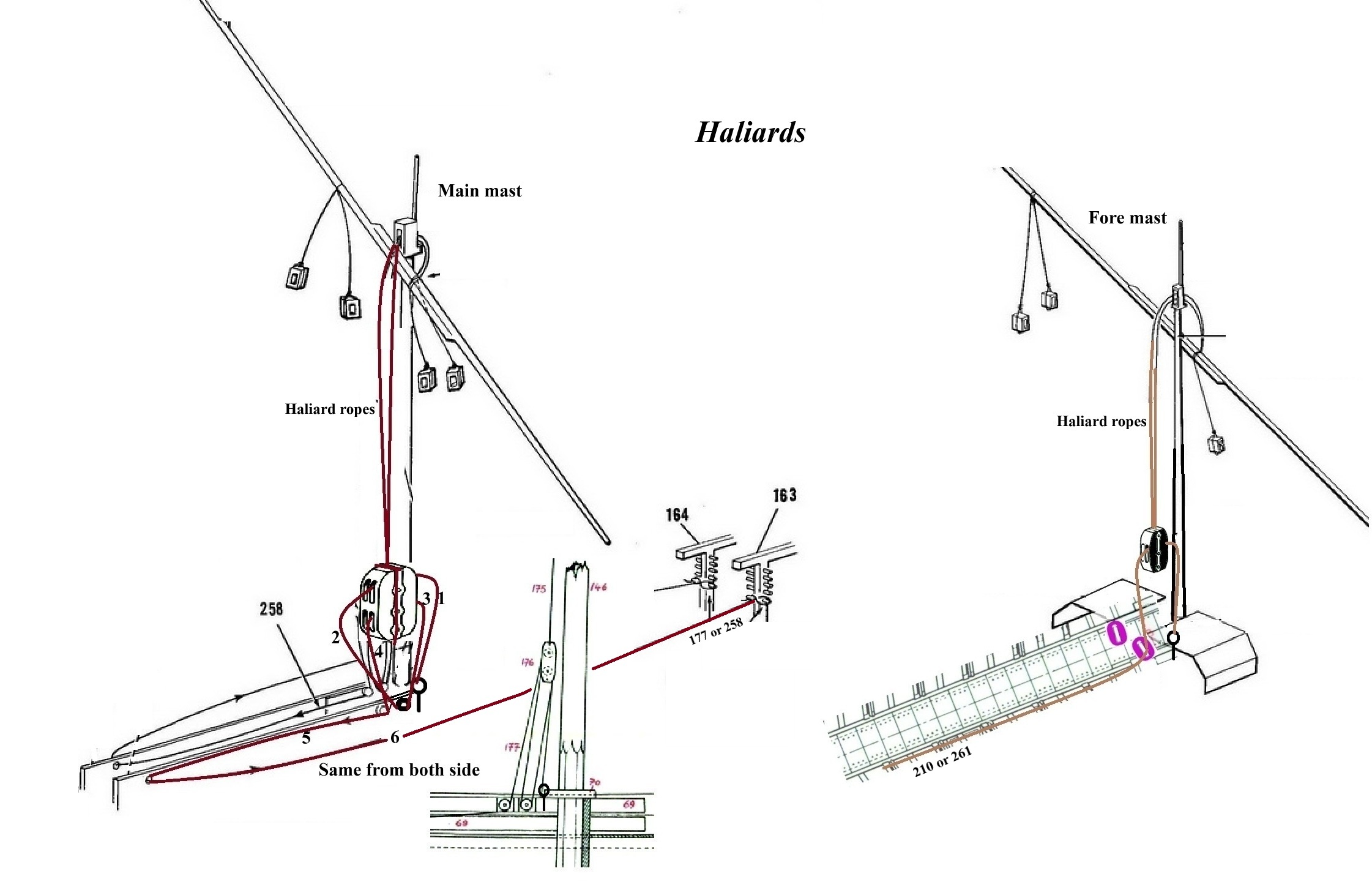
The yards were hoisted to approximately two-thirds of the mast height by halyard ropes passing through blocks at the mastheads. These ropes were attached to the blocks of the hoisting tackles.
A large four-sheave block is fitted at the mainmast. The tackle ropes on both the starboard and port sides passed through this block.
The hauling ropes started at the foot of the mast, passed through the large four-sheave block and then through blocks attached to the inner sides of the central walkway. From there, they continued aft beneath the walkway planking on both sides. They then passed through blocks in the sides of the walkway at the last bench, where they emerged from beneath the planking. The ropes were subsequently led along the rowing benches to the forward superstructure, where they were made fast.
This routing allowed the oarsmen along the entire length of the vessel to pull together and hoist the heavy main yard.
The fore yard was hoisted in a similar way. The hauling ropes were secured at the foot of the foremast and passed through a large double block suspended from the halyard ropes running through the masthead blocks.
After passing through the large double block, the hauling ropes returned to blocks attached to the sides of the central walkway. They were then led along the benches to the stern, where they were made fast. This arrangement again allowed the oarsmen along the length of the vessel to pull together and hoist the fore yard.
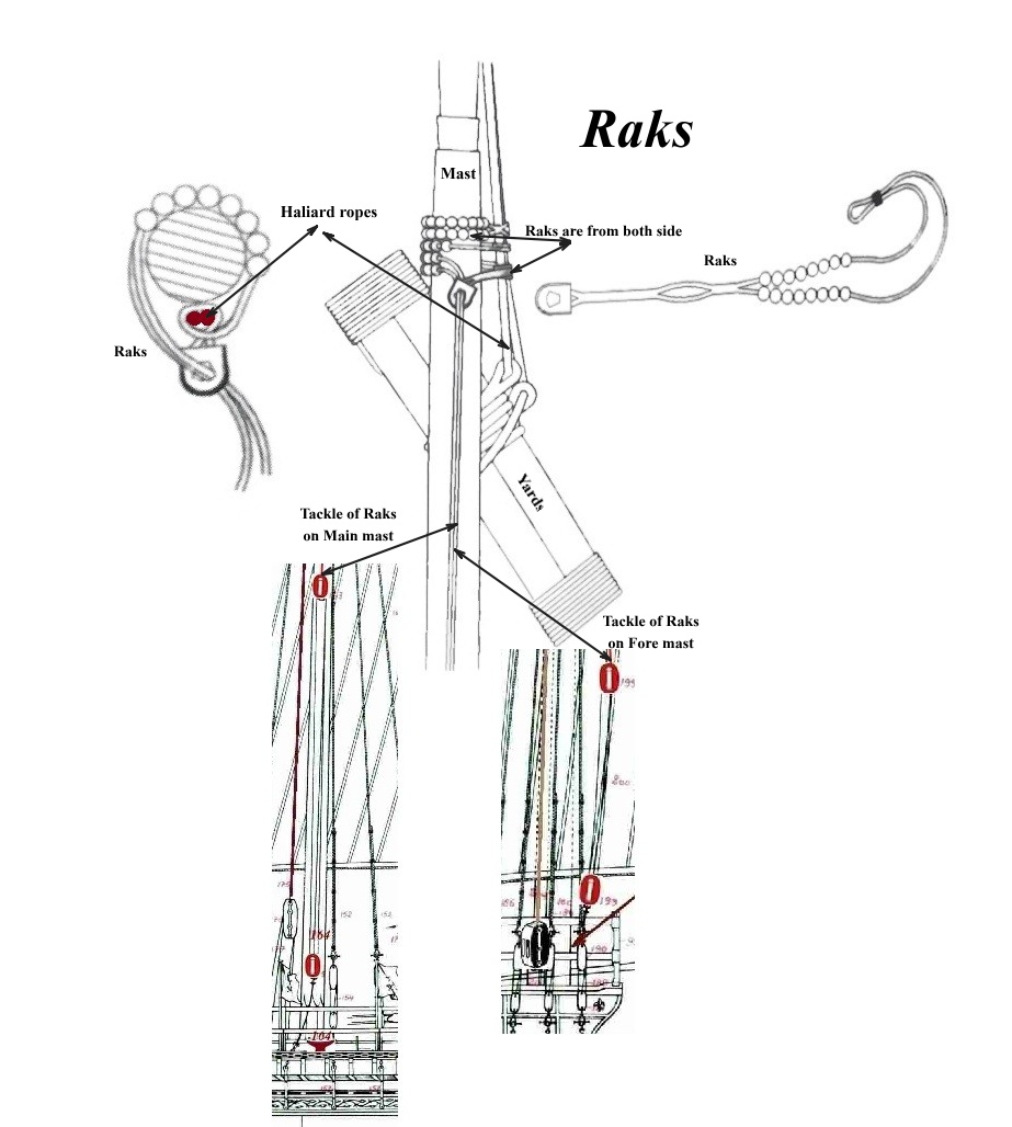
Although this is not directly apparent from the plans, the rigging description states that the yards were suspended from the masts outside the shrouds. This arrangement allowed the yards to be turned as required, depending on the wind direction and the vessel’s course. See Fig. 3.
To hold the yards close to the masts and transfer the pull of the sails to them, the yards were secured by parrels. These parrels, controlled from both sides of the vessel, encircled not only the rope from which the yard was suspended but also the entire group of shrouds.
Tightening or easing the parrels allowed the yard to move closer to or farther from the mast and to turn into the desired position. The parrels were tensioned by tackles attached to the sides of the vessel. The upper parrel ropes are numbered 146 and 198.
Sheets and Yard-Control Lines – Yardpeak and Brail[3]
The most difficult part of rigging the model was determining the positions and attachment points of the sheets and yard-control lines. These points were not marked anywhere on the plan, and without assistance I would certainly not have been able to draw them correctly.
I would still welcome advice from anyone who has a different view of how these arrangements should be represented. I am not an expert in this field and have simply tried to make the best possible use of the available material.
The sheets and yard-control lines were attached between the rowing benches, behind the posts supporting the benches at the outer longitudinal structure known as the apostis. The standing ends of the ropes were secured to metal fittings. Their free ends, used for hauling or easing, were made fast at the appropriate belaying points or directly to the vessel’s structure.
One further point is worth keeping in mind: the rowing benches were numbered from aft. Bench 1 was therefore the aftermost bench in the row.
Upper Yard-Control Lines
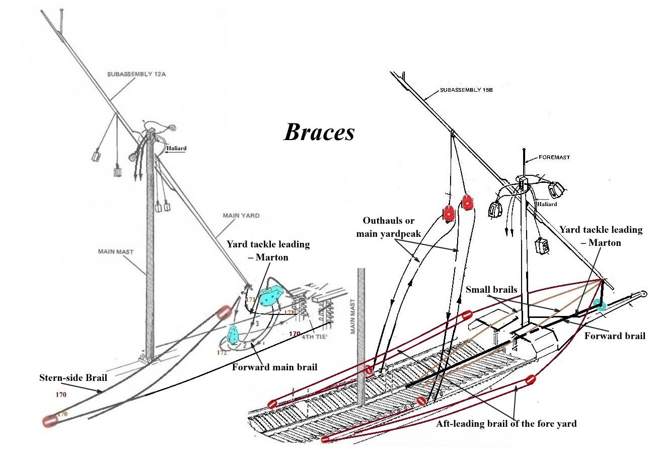
The upper yard-control lines, labelled “Outhauls or main yardpeak”, were attached approximately one-quarter of the yard’s length from its upper end. They led down towards both sides of the vessel through tensioning tackles. These lines are numbered 165 for the mainsail and 201 for the foresail.
The sails exerted a considerable pull. To turn the yards into the required position, their lower ends were controlled by three ropes. These were repositioned according to the angle of the yards, the wind direction and the vessel’s course. Each yard was controlled by a forward and an aft tackle. Its position was then secured by a very heavy rope labelled “Yard tackle leading – Marton (Fr.)”[4].
Main Yard Rope Routing – Fig. 4
Yard Tackle Leading – Marton (Fr.) – 171
This was a heavy rope used to secure the main yard in its final position. It was tied to the lower side of the main yard, and its other end was hauled taut and made fast at the belaying points on the forward superstructure.
Lower Aft Control Line – Stern-side Brail – 170
This line is attached to the lower end of the main yard. A block is suspended from the line and tensioned by a tackle.
The tackle rope starts at bench 5, passes through this block and then runs outside the shrouds to a block at bench 1. From there, it returns towards the bow, where it is made fast.
Depending on the wind direction and the vessel’s course, this arrangement is positioned on either the starboard or port side.
Lower Forward Control Line – Forward Main Brail – 172
This is a tackle attached to the lower side of the main yard and tensioned towards the bow, on either the starboard or port side according to the vessel’s course and the wind direction. The hauling end of the tackle rope was led along the benches to bench 1, where it was made fast.
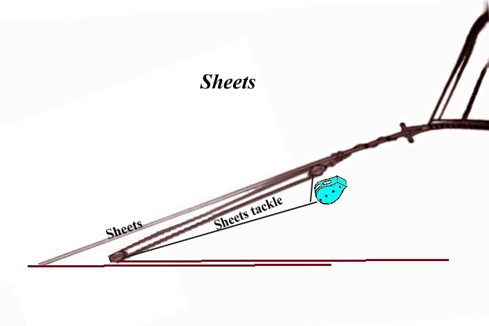
Main Sheet – 174 – Fig. 5
The main sheet tensioned the lower aft corner, or clew, of the mainsail. The arrangement consisted of two parts.
The principal part was a very heavy rope attached to the clew of the sail. After being tensioned by a tackle, it was made fast at a belaying point at bench 1, on either the starboard or port side according to the wind direction and the vessel’s course.
To tighten this heavy rope sufficiently, a tackle was suspended from a rope wrapped around it. The lower block of this tackle was hooked into an eye at bench 1.
The hauling end of the tackle rope was then led along the benches to a belaying point on a post of the forward superstructure. This allowed the oarsmen along the entire length of the vessel to help tension the rope.
Fore Yard Rope Routing
Forward Brail – 213
This was a heavy rope used to secure the fore yard in its final position. It was tied to the lower part of the fore yard, passed through a block hooked to the vessel’s projecting bow structure, and then continued aft to a belaying point at bench 20.
Lower Aft Control Lines – Aft-leading Brail of the Fore Yard – 206
These ropes are attached to the lower end of the fore yard and lead to both sides of the vessel.
A block is suspended from each rope and tensioned by a tackle. The tackle rope starts at bench 13, passes through the suspended block, then runs outside the shrouds to a block at bench 10. From there, it returns towards the bow to a belaying point at bench 20.
Lower Forward Control Lines – Small Brails – 212
These ropes are attached to the lower end of the fore yard and lead to both sides of the vessel above the forward superstructure. From there, they continue aft to belaying points along the edges of the central walkway at bench 26.
Fore Sheet – Sheet of the Small Foresail – 207
The fore sheet tensioned the lower aft corner, or clew, of the foresail. Like the main sheet, its arrangement consisted of two parts.
The principal part was a very heavy rope attached to the clew of the sail. After being tensioned by a tackle, it was wrapped once around the foot of the mainmast and made fast at a belaying point at bench 21, along the edge of the central walkway.
To tighten this rope sufficiently, it was tensioned by tackle 208, suspended from a rope wrapped around the heavy sheet.
The lower block of this tackle was hooked into an eye at bench 6, along the edge of the central walkway. The hauling end of the tackle rope was led along the benches to a belaying point at bench 9, also at the edge of the central walkway.
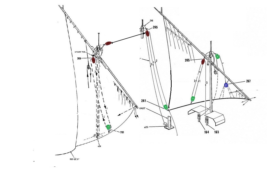
Gathering Up the Sails – Clew Line – Fig. 6
The arrangement for gathering up the sails was very simple. Only one gathering line was used for the mainsail. It was suspended from the masthead and led to a point on the foot of the sail approximately one-third of the way along from its aft end.
Although the foresail was smaller, several lines were used to gather it up. As with the mainsail, one line was suspended from the masthead and led to a point on the foot of the sail approximately one-third of the way along from its aft end.
Another gathering line was suspended from the masthead to serve the forward part of the foresail. It led towards the lower edge of the sail, where a suspended block connected it to several branches attached along the foot.
The most distinctive feature, however, was a gathering line suspended from the mainmast head and led to the aft corner of the foresail. It then returned to a block near the mainmast head and was finally made fast at the foot of the mainmast.
Conclusion and Acknowledgements
The description above shows how significantly the rigging and handling of a Mediterranean galley differed from the more familiar arrangements found on other vessels. Its distinctive terminology reflects these differences.
I hope I have explained the positions and functions of the individual ropes clearly, and that I have interpreted their routes correctly.
As mentioned earlier, I could not have done this without considerable assistance. I would therefore like to thank fellow modeller Joska, who provided both expert advice and the reference material on which I was able to draw.
Glossary
- [1] Backstays – Parduby / Parduny
- Ropes supporting a mast from aft or from the sides. They help stabilise the mast and resist loads acting mainly aft and sideways. “Parduby” and “parduny” are the Czech terms used in the original text.
- [2] Parrel – Raks
- A rope arrangement that holds a yard close to the mast while allowing it to move and turn. Tightening or easing the parrel changes the yard’s position relative to the mast. “Raks” is the Czech term used in the original text.
- [3] Yard-Control Lines – Halže / Brail
- Lines used to control and adjust the lower part of a yard or the lower corner of a sail. On lateen-rigged galleys, they play an important role in setting the yard according to the wind direction and the vessel’s course. The Czech text uses “halže”; the original labels reproduced in this article include “Stern-side Brail” and “Forward brail”.
- [4] Yard Tackle Leading / Marton
- A label used for a heavy rope or rope arrangement that secures the yard in its final position. In this article, the arrangement is described under number 171 for the main yard and number 213 for the fore yard.